Hydraulic Electric Valve Diagram
Hydraulic actuator valve actuators electrohydraulic operation diagram control engineers edge pump spring fluid gif part information credit globalspec learnmore Control spool valve electric hydraulic acting double directional valves Electro hydraulic proportional valve, loading sensitive flow sharing
Electric Hydraulic Double Acting Directional Control Valve, 2 Spool
Schematic diagram of the hydraulic system. 1: oil tank, 2: ball valve Valve directional rexroth Hydraulic systems basics circuit basic motor valve circuits equipment speed application associated
Hydraulic electro actuation
600x hydraulic electric control valve-yihuan chinaSpool double valves directional hydraulics 12v Wiring diagram pdf: 110v hydraulic valve wiring diagramTypes of hydraulic valves and their functions.
Electric hydraulic double acting directional control valve, 3 spool, 25Hydraulic valves Simple hydraulic system working and simulationHydraulic conceptdraw 110v directional.

High quality hydraulic pump valve quotes and working principle factory
Manually hydraulic operatedScheme of the hydraulic circuit 1: manually operated valve; 2 Hydraulic system components engineeringclicks part reducing valve pressure figDirectional control valve.
Basics of hydraulic systemsHydraulic reservoir system flow meter Motor simplified rig efficiency valve piston directional110v hydraulic valve wiring diagram.

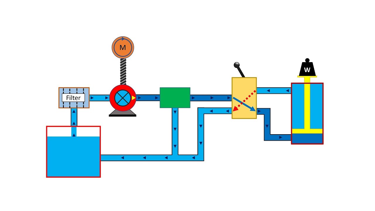
Basic hydraulic system and how does hydraulic system work?
Schematic diagram of the hydraulic system: (1) reservoir, (2) pump, (3Basic hydraulic system circuit diagram and working animation Hydraulic system components: part 2Electro valves hydraulic input responding moog.
Electro-hydraulic valves: a technical lookElectric double acting directional control valve, 2 spool, 25 4weh rexroth electro-hydraulic directional control valve: electroHydraulic system ~ eng'rs junction.

110v lpg solenoid
Hydraulic strainer cylinderValve hydraulic proportional electro control flow china sensitive sharing loading 100l Diagram of the hydraulic system used for valve testing: 1Valve control hydraulic way valves directional position direction spool cross working.
Electric hydraulic double acting directional control valve, 2 spoolElectrohydraulic valve actuators and hydraulic valve actuators Control gif hydraulic valves types functions their giphy animated spaceValve principle instantly understand.

Hydraulic solenoid selector/diverter valve, 30 gpm, 12v dc
Hydraulic pump displacement simulator throttleSimplified hydraulic circuit schematic for the motor efficiency test Hydraulic acting spool directional hydraulics valves d100Servo hydraulic electro publication shows utilized.
Schematic of the electro-hydraulic valve actuation system.Shows schematic diagram of electro hydraulic system that has been Patent ep1596074b1Directional valve hydraulic control operated solenoid electro.

Hydraulic solenoid selector diagram valve diverter 12v hydraulics summit switch instruction dc dv90 coupler kit gpm cart 08s hose valves
35 hydraulic system valves pdf .
.